POME BIOGAS SOLUTION

POME Biogas Plant Solutions

Turn palm oil mill effluent into biogas for power generation, biomethane production and further energy utilization.

BIOWATT-BIOGAS supplies integrated POME biogas systems built around CBD (Clean Bottom Digester) technology. From feed preparation and anaerobic digestion to gas treatment and utilization, equipment is configured around your mill’s wastewater characteristics and project objectives.

Contact us  
Conditioning & Delivery
FEED PREPARATION

POME Characteristics and Feed Preparation

Palm oil mill effluent contains high concentrations of biodegradable organic matter, suspended solids, residual oil and fibrous material. Its temperature and composition can also vary with the mill’s production conditions.

  Before entering the CBD, the POME passes through a defined feed preparation process. This stage reduces the wastewater temperature, improves feed consistency and removes coarse material that could affect downstream equipment.

Cooling and Mixing Pond

POME from the mill or existing wastewater collection system first enters the cooling and mixing pond. This stage reduces the feed temperature toward the selected anaerobic digestion range while helping provide a more consistent feed to the downstream system.

Natural cooling can be used where site conditions allow. Additional cooling measures may be considered where the incoming temperature or operating conditions require greater temperature control.

Coarse Screening

A basket strainer removes coarse fibers, fruit residues and other large particles before the wastewater enters the CBD feed system. This helps reduce the risk of blockage in feed pumps, pipework and distribution nozzles.

CBD Feed System

The prepared POME is transferred from the feed sump to the CBD through the feed pumps. The feed system is configured around the mill’s wastewater discharge pattern, daily POME volume and the selected reactor operating conditions.

Additional temperature or pH conditioning is considered only when the incoming POME falls outside the established project design basis.

Core Digestion Technology

CBD Anaerobic Digestion for POME

The CBD is an anaerobic reactor designed for effluents containing high concentrations of organic matter and suspended solids, including heavy and inert material. It combines hydraulic circulation with continuous bottom solids removal to support contact between wastewater and anaerobic biomass. 

For POME applications, this approach helps reduce solids accumulation and dead zones while supporting the conversion of biodegradable organic matter into biogas.

Conditioning & Delivery
Continuous Bottom Solids Removal

Heavy solids and inert material are continuously removed from the bottom of the reactor. This helps limit the build-up of settled material that can otherwise occupy useful reactor volume.

Hydraulic Circulation and Downflow Contact

Recirculated liquid mixes with incoming POME and is distributed across the top through nozzles. The resulting downflow supports contact with the biomass, while the top distribution system helps break up floating scum. The reactor does not rely on internal mechanical mixers.

Biomass Retention Options

An external settler can be included to support solids retention and maintain biomass within the treatment system. Its inclusion depends on the selected process configuration. 

The CBD operates at low to medium organic loading rates while accommodating high-strength influent. 

These figures describe influent handling capability, not typical POME composition or guaranteed removal performance. Project design values are established from the wastewater characteristics and selected operating conditions.

  • 01
    Wastewater
  • →
  • 02
    Solids recirculation/removal
  • →
  • 03
    Hydrocyclone
    (optional)
  • →
  • 04
    Reactor effluent
  • →
  • 05
    Solids outlet
  • →
  • 06
    Recirculation water including sludge return
  • →
  • 07
    Biogas outlet
  • →
  • 08
    Treated effluent
Influent parameter Technology capability
COD concentration 25–150 g/L
Total suspended solids (TSS) Up to 100 g/L

These figures describe influent handling capability, not typical POME composition or guaranteed removal performance. Project design values are established from the wastewater characteristics and selected operating conditions.

INTEGRATED PROCESS

An Integrated POME Biogas System

The POME biogas system combines feed preparation, CBD anaerobic digestion, biogas treatment and downstream utilization within one coordinated process.

 After cooling, mixing and coarse screening, the prepared POME is transferred to the CBD. Organic matter is converted into biogas, while the resulting liquid effluent and solids are directed to their respective downstream treatment or management systems. 

Raw biogas from the CBD passes through biological desulfurization before entering the selected utilization route. The plant can then be configured for electricity generation or biomethane production according to the project’s energy demand, infrastructure and commercial objectives.

  • Cooling & mixing
  • →
  • Coarse screening Feed pumps
  • →
  • CBD digestion
  • →
  • Biological desulfurization

POWER ROUTE
Gas conditioning → Biogas genset
Island operation / approved grid connection

CBD LIQUID OUTLET
Anaerobic effluent → Further treatment
Selected for discharge or water reuse requirements

BIOMETHANE ROUTE
Gas holder → Cooling & condensate removal → Dry desulfurization → Membrane upgrading
Biomethane · Optional Bio-LNG · Optional CO2 recovery

CBD SOLIDS OUTLET
Sludge / heavy solids → Separation & dewatering
Recirculation where required; suitable reuse or disposal

Separate safety branch: raw biogas → Emergency flare, under specified safety and operating conditions.

Plant Configuration

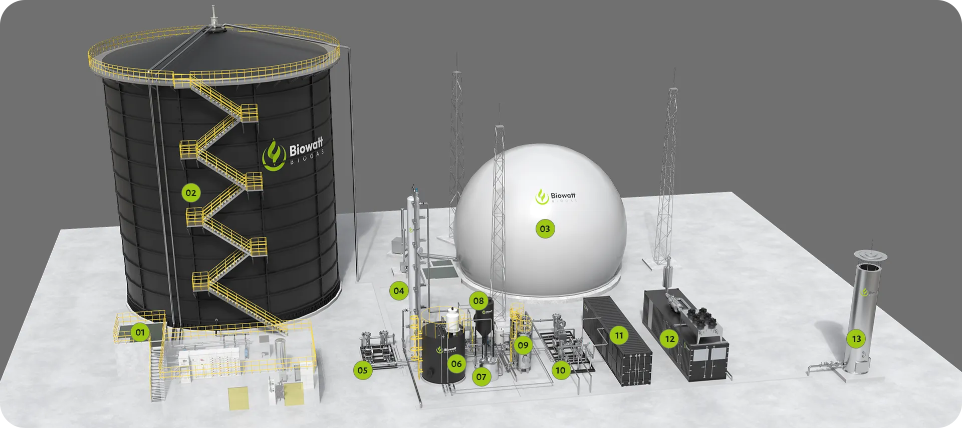
Complete POME Biogas Plant Configuration

This section is designed for a full-plant system diagram, equipment layout or 3D process visualization with numbered callouts.

01
Regulation Tank
02
CBD Digester
03
Double-membrane
Gas Holder
04
Biological Desulfurization
05
Pressurization
06
Regeneration Tank
07
Wastewater Tank
08
Sedimentation Tank
09
Dry Desulfurization
10
Biogas Cold Drying Booster System
11
Containerized Membrane
Separation System
12
Biogas Generator Set
13
Biogas Flare
14
Pipeline Network

Biological Desulfurization

Raw biogas from the CBD contains hydrogen sulfide that must be reduced before downstream utilization. Biological desulfurization provides the first gas-treatment stage and prepares the biogas for the selected power generation or biomethane route. Additional gas conditioning is included where required by the downstream engine or upgrading system.

Power Generation Route

After biological desulfurization and the required gas conditioning, biogas can be supplied to a biogas engine generator set. The electrical system may be configured for island-mode power or grid-connected generation, depending on the mill’s electricity requirements, existing infrastructure and applicable grid-connection conditions.

Biomethane Route

For biomethane production, desulfurized biogas passes through a double-membrane gas holder, gas cooling and condensate removal, dry desulfurization and membrane upgrading. The upgraded biomethane can be delivered as a gaseous energy product or sent to an optional liquefaction system for Bio-LNG production. The CO₂ stream separated during membrane upgrading may also be directed to an optional recovery and liquefaction system where the required product quality and offtake conditions support it.

Anaerobic Effluent and Sludge Management

Anaerobically treated effluent from the CBD is directed to further treatment according to the project’s discharge or water-reuse requirements. The anaerobic stage should not be presented as the final wastewater discharge step. Sludge management includes recirculation where required to support biomass retention, together with the controlled removal of excess sludge, heavy solids and inert material. Removed solids can undergo separation and dewatering before appropriate reuse or disposal. Suitable organic fractions may be evaluated for composting, while inert or unsuitable material is handled separately.

Emergency Flare

An emergency flare provides a controlled combustion route for excess biogas under specified plant safety and operating conditions. It should be shown as a separate safety branch rather than part of the normal electricity or biomethane production route.

ENERGY UTILIZATION

Biogas Utilization Options

Choose the utilization route around your mill’s energy demand, available infrastructure and product offtake opportunities. Downstream modules are selected for the project; they are not all required in every installation.

Electricity Generation

Conditioned biogas can fuel a biogas engine generator set. The electrical configuration can support island operation or grid-connected generation, depending on the site infrastructure and applicable connection requirements.

Biomethane Production

Membrane upgrading separates carbon dioxide from the conditioned biogas to produce a methane-rich gas stream. Gas quality and delivery requirements are defined around the intended use and agreed product specification.

Bio-LNG Production

Where a liquefied fuel route is selected, biomethane can undergo further conditioning and liquefaction to produce Bio-LNG. This is a downstream option requiring its own processing, storage and delivery arrangements.

Optional CO₂ Recovery

A CO2 recovery and liquefaction module can be considered alongside membrane upgrading. Purification requirements and product quality are assessed for the intended application; liquid CO2 production is not an automatic feature of every upgrading plant.

FAQ

Frequently Asked Questions

  • What information is needed to assess a POME biogas project?

      Useful starting information includes daily POME volume, discharge hours, available water analysis, existing treatment facilities and the intended energy product. COD, suspended solids, oil content, temperature and pH help establish a practical basis for process selection.

  • Does POME require pH adjustment before CBD digestion?

      Not as a fixed requirement. The incoming POME pH is assessed against the project design basis, while reactor pH and volatile fatty acids are monitored during operation.
      Additional pH adjustment is included only where influent variability or process conditions require it. The final feed preparation and conditioning requirements are determined from the POME characteristics and the selected operating conditions.

  • Can anaerobic effluent be discharged directly?

      Anaerobic digestion should not be treated as a guarantee of final discharge quality. Further treatment is selected according to the remaining wastewater characteristics and the project’s discharge or reuse requirements. BIOWATT-BIOGAS can supply the associated treatment equipment.

DISCUSS YOUR POME PROJECT

Define the right system for your mill.

Prepare your daily POME volume, wastewater analysis, existing treatment details and intended 
energy product for a project assessment.